Product Overview
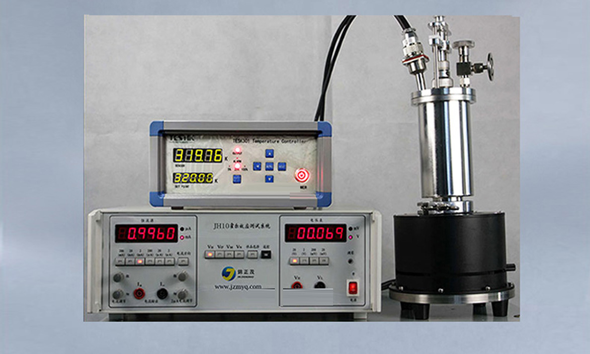
This system consists of four parts: CVM200 variable temperature teaching Hall measurement system, TESK301 temperature controller, liquid nitrogen cryostat, and a rotating magnet. It can complete teaching experiments measuring the Hall effect of Hall samples under different temperature conditions.
This instrument system comprises a reversible permanent magnet, T9015W variable temperature cryostat, TESK301 temperature controller, and JH10 Hall effect instrument. It is used for demonstrations and student experiments on the Hall effect and its applications, carrier type, and carrier type transition. It can also be used for scientific research by installing user samples using the reserved sample leads inside the cryostat, such as variable temperature magnetoresistance, superconductivity, resistance temperature characteristics, variable temperature photoelectric or variable temperature magneto-optical (requires optional tail sleeve with optical window). It features wide application, low cost, and ease of use.
The specially developed JH10 Hall effect instrument (hereinafter referred to as JH10 meter) integrates a constant current source, a 4.5-digit microvolt meter, and the complex switching relays and switches for Hall measurement into one unit, greatly simplifying experimental wiring and operation. The JH10 can also be used independently as a 4.5-digit constant current source and microvolt meter.
Main Technical Specifications
- Magnetic Field: >3900 Gauss
- Sample Current: 10 nA ~ 199.99 mA
- Measurement Voltage: 1 μV ~ 19.999 V
- Minimum Temperature Resolution: 0.01 K
- Temperature Measurement Error: <0.5 K
- Variable Temperature Range: 80 K ~ 320 K (optional), Room Temperature ~ 500 K (optional)
- Cryostat Liquid Nitrogen Capacity: 450 mL
System Installation and Connection
After receiving the goods, inspect the package for obvious shipping damage before starting installation and debugging. First, place the permanent magnet on the workbench, then insert the cryostat into the center hole of the permanent magnet. During the experiment, place the stainless steel base of the reversible permanent magnet flat on the workbench, with the top elongated sliding hole positioned horizontally to the left front of the experimenter. Rotate the middle black magnet so that the trademark faces the experimenter. At this point, the magnetic field direction is perpendicular to the trademark, with the N pole near the experimenter and the S pole opposite. Rotate the middle black magnet 180° to reverse the magnetic field. Slide the cryostat leftward in the elongated sliding hole to move the sample to a region without magnetic field.
Connect the cryostat to the temperature controller and JH10 meter using dedicated signal cables. Set the voltage range of the JH10 meter to 20 V and the current source to 2 mA. Plug in the instrument power cord and turn on the power. To prevent electric shock, ensure the power supply has a reliable dedicated ground wire. After powering on, if the output indicator of the temperature controller lights up, the temperature will continue to rise. You can change the set temperature via the panel to lower it. If the temperature becomes uncontrollable, immediately power off and restart the temperature controller. If the fault recurs, contact our company.
Test Samples
Samples in this instrument:
1 Sample 1 (S1): Lakeshore HGT-2100 high-sensitivity Hall plate,
Maximum operating current ≤10 mA, sensitivity at room temperature: 55-140 mV/kG
Sample 2 (S2): Customers can install their own samples according to the wiring definition.
Instrument Use and Experimental Methods
(1) Magnetic Field Calibration
S1 in the system is a Hall probe calibrated at room temperature. At room temperature, select sample S1 using the switch, and place the cryostat at the center of the reversible permanent magnet, with the cryostat vacuum port perpendicular to the label surface. After powering on, quickly adjust the constant current source output to mA. The microvolt meter reading on the JH10 meter is the magnetic field in Tesla. At this time, the JH10 functions as a gaussmeter with the probe mounted on the cryostat cold finger, which can be used to measure spatial magnetic fields. The maximum current for the Hall probe must not exceed 10 mA.
(2) Hall Measurement at Room Temperature
Connect the 19-core cable to the cryostat, select sample S2 with the sample switch, adjust the sample current to 10.00 mA, and warm up for half an hour. During measurement, place the cryostat at the center of the magnetic field, press the VH switch to measure Hall voltage VH1. If the voltage is small, switch to the 2 V or 200 mV range. To ensure the magnetic field is perpendicular to the sample, hold the left and right support plates with both hands and slightly rotate the black square iron yoke magnetic circuit to maximize VH. Press the current reversal switch to measure VH2. Rotate the black permanent magnet 180° and measure VH3. Reverse the current again and measure VH4. Slide the cryostat horizontally to the left so that the magnetic field at the sample is zero, press the VM switch to measure VM1. Press the current reversal switch to measure VM2. Press the VN switch to measure VN1. Press the current reversal switch to measure VN2.
(3) Variable Temperature Measurement
Remove the cryostat center rod, inject liquid nitrogen (the amount depends on the number of measurement points). For specific precautions, refer to the T9015W low-temperature cryostat instruction manual. If you do not wish to start measurement from 80 K, you can first set the temperature control to 270 K, then add liquid nitrogen and promptly insert the center rod to perform temperature control experiments at higher temperatures. During temperature control, rotate the center rod clockwise to the lowest position, then rotate back about 180° to 720° to set the temperature via the temperature controller. After the temperature stabilizes, repeat the measurement process in step 2 to obtain Hall parameters at that temperature point. Change the set temperature to measure Hall parameters at another temperature point. Raising the center rod increases cooling capacity, suitable for rapid cooling and low-temperature experiments. Temperature control accuracy is related to PID parameters; adjust the center rod height appropriately to improve control accuracy in different temperature zones.
(4) Safety Precautions
① Regularly check and ensure proper instrument grounding.
② Do not touch extremely cold surfaces or the liquid nitrogen funnel with wet hands to prevent skin from freezing and sticking to cryogenic surfaces, which can cause severe frostbite! Wear thick cotton gloves when pouring liquid nitrogen. If frostbite occurs, immediately rinse with plenty of tap water and treat the wound as a burn. ③ After the experiment, be sure to loosen and lift the center rod to prevent the white PTFE plug from expanding due to heat and damaging the cryostat.